
Engine Mount Design Optimization Using FEA
ENGINE MOUNT DESIGN OPTIMIZATION USING FINITE ELEMENT ANALYSIS

AEG applied Finite Element Analysis (FEA) to optimize an automotive engine mount, achieving a 16.7% reduction in mount area while maintaining the original stiffness and keeping hydrostatic pressure at critical points within acceptable limits.

Project Overview

American Engineering Group (AEG) conducted a Finite Element Analysis (FEA)-based design optimization study of an automotive engine mount. The objective was to reduce the mount’s area while maintaining its original stiffness and keeping hydrostatic pressure at critical points within acceptable limits. Through structural analysis and design optimization, the study achieved a documented 16.7% reduction in mount area.

Engineering Challenge

The primary engineering challenge was to reduce the engine mount’s area without compromising its original stiffness. The optimized design also needed to maintain hydrostatic pressure at critical locations within an admissible range, requiring careful consideration of structural behavior and design constraints.

Engineering Approach

AEG used a Pro/E model, Finite Element Analysis (FEA), and design optimization to evaluate the engine mount. The optimization process focused on minimizing the mount’s area while preserving the original stiffness and satisfying the specified hydrostatic pressure constraints. The portfolio documents the initial model, FEA analysis, and resulting optimized design.

Application

Automotive Engine Mount

Engineering focus

Design Optimization

Key Result

16.7 % reduction in mount area

Design Requirements

✔  Minimize mount area

✔  Maintain original stiffness
✔  Keep hydrostatic pressure within admissible limits

Models and Analysis

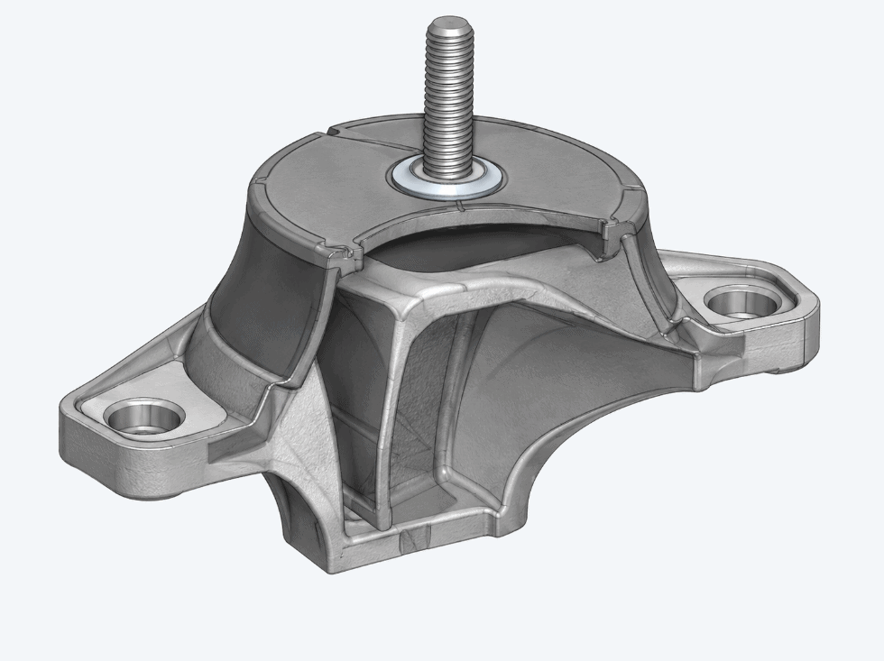
Initial automotive engine mount CAD model showing mounting brackets and central threaded stud
1. Pro/E Model

Initial engine mount geometry used for FEA and optimization
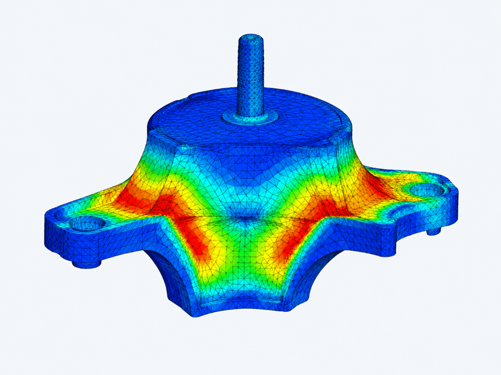
Finite element analysis illustration of an automotive engine mount showing simulation mesh and color-coded contours
2. FEA Analysis

Finite element model used to evaluate stiffness and hydrostatic pressure at critical locations.
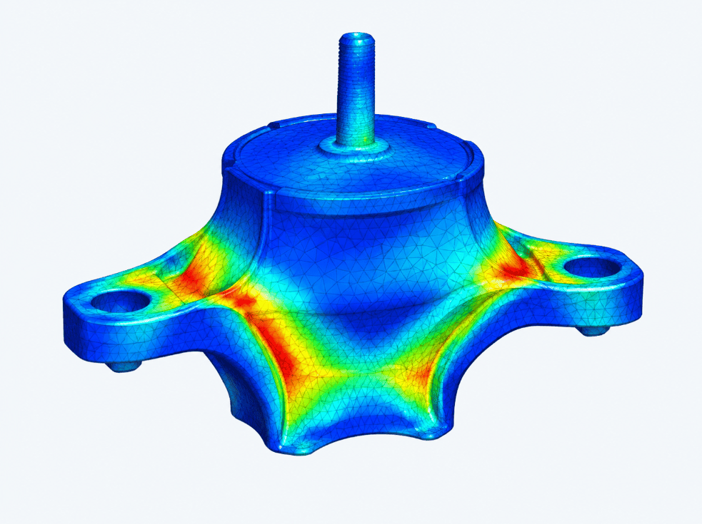
Conceptual optimized automotive engine mount geometry with finite element mesh and color-coded analysis contours
Optimized Design

Revised geometry with reduced area while maintaining stiffness and acceptable hydrostatic pressure.

Engineering Approach

AEG used a Pro/E model, Finite Element Analysis (FEA), and design optimization to evaluate the engine mount. The optimization process focused on minimizing the mount’s area while preserving the original stiffness and satisfying the specified hydrostatic pressure constraints. The portfolio documents the initial model, FEA analysis, and resulting optimized design.

16.7%

Reduction in Mount Area

Stiffness maintained Hydrostatic pressure within acceptable range.

Conclusion

The Engine Mount Design Optimization study demonstrates how Finite Element Analysis (FEA) can support engineering design improvements while maintaining critical performance requirements. By combining structural analysis with design optimization, AEG achieved a documented 16.7% reduction in engine mount area, while maintaining the original stiffness and keeping hydrostatic pressure at critical points within admissible limits.

This case study highlights the value of simulation-driven engineering in evaluating design alternatives, optimizing component geometry, and supporting more efficient automotive component development.

Call Now Button